Table of Contents
Learning how to wire a winch switch on an ATV is an essential skill for any off-road enthusiast who wants to ensure their recovery equipment is ready when needed. While the winch itself provides the pulling power, the switch is your critical interface that transforms electrical commands into mechanical action. A properly installed winch switch ensures reliable operation when you’re stuck in mud, sand, or challenging terrain where recovery options are limited. This comprehensive guide will walk you through the entire process—from understanding the fundamental electrical principles to selecting the right components and executing a professional-grade installation. Whether you’re adding a switch to an existing winch or completing a new winch installation, following these methodical steps will ensure your ATV recovery system operates safely and effectively when you need it most.
Understanding ATV Winch Switch Fundamentals
Before handling any wires, it’s crucial to understand what a winch switch does and why proper installation matters for both performance and safety. The switch serves as the control point between your ATV’s electrical system and the winch motor, allowing you to activate the winch in both directions—winding in and winding out.
Unlike simple accessories like lights, a winch draws substantial electrical current, often exceeding the capacity of a standard toggle switch. This is why most winch switches don’t handle the main power directly but instead control a relay (or solenoid) that acts as a high-current switch. The relay receives a low-current signal from your switch and uses an electromagnetic coil to open or close heavy-duty contacts that carry the full power to the winch motor .
This setup offers several critical advantages:
- Safety: Keeps high-current wiring away from the operator compartment
- Switch Protection: Prevents switch failure from excessive current
- Control Flexibility: Allows for remote switch mounting locations
- Reliability: Ensures consistent performance under heavy electrical loads
Understanding this relationship between your switch, relay, and winch motor is fundamental to planning and executing a correct installation that will provide years of trouble-free service.
Planning Your Winch Switch Installation
Proper planning is the most overlooked yet most critical phase of any electrical installation. Taking time to plan your winch switch setup will prevent common mistakes and ensure a safe, reliable outcome.
Component Selection
Your winch switch system requires several key components working together:
- Winch Switch Type: Choose between momentary rocker switches (returns to center when released) or maintained switches (stays in position). Momentary switches are generally safer for winch operation as they automatically stop when released. Consider waterproof switches specifically designed for ATV environments .
- Relay/Solenoid Pack: Most winches include an appropriate relay pack. If not, select one rated for at least the maximum amperage draw of your winch motor. A typical 2500-4500 lb ATV winch may require a relay rated for 200-300 amps.
- Wire Selection: Use automotive-grade stranded copper wire. For the high-current circuit between battery and winch, 4-6 gauge wire is typically appropriate. For the switch control circuit, 14-16 gauge wire is sufficient .
- Circuit Protection: Install an appropriate fuse or circuit breaker near the battery connection point. The rating should match your winch’s maximum current draw while protecting the wire gauge used.
- Connectors: Use quality crimp connectors with proper crimping tools. Weatherproof connectors are ideal for ATV applications where exposure to elements is inevitable .
Tools and Equipment Needed
Gathering the right tools before starting will make the process smoother:
- Wire cutters and strippers
- Quality crimping tool
- Heat gun (for heat-shrink tubing)
- Multimeter for testing
- Various wrenches and sockets
- Cable ties and mounting hardware
- Drill and bits (if creating new mounting holes)
- Electrical tape and dielectric grease
Power Requirements Assessment
Check your ATV’s electrical system capacity to ensure it can handle the winch load. A typical 2500-4500 lb winch can draw 150-300 amps under heavy load. Ensure your battery is in good condition and your charging system can replenish the power used during winching operations. For frequent winch use or high-capacity winches, consider upgrading to a high-output alternator or larger battery .
Step-by-Step Wiring Installation Guide

With planning complete and components gathered, you’re ready to begin the installation process. Follow these steps methodically for a professional result.
Safety First Precautions
Before starting any electrical work:
- Disconnect the negative battery terminal to prevent accidental shorts
- Work on a clean, dry surface with good lighting
- Wear safety glasses when drilling or cutting
- Keep a fire extinguisher nearby as a precaution
- Double-check all connections before reapplying power
Mounting the Winch Switch
Choose a location for your switch that is:
- Easily accessible while operating the ATV
- Protected from accidental activation
- Sheltered from direct exposure to water and debris
- Convenient for routing wiring to the relay and power source
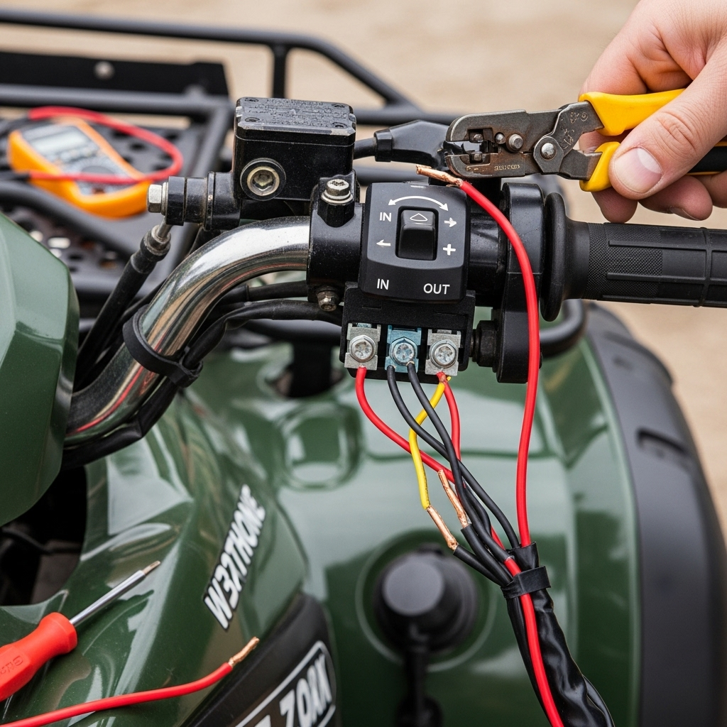
Common locations include the dashboard, handlebar cluster, or a dedicated switch panel. Ensure there’s adequate space behind the panel for the switch and wire connections. Use the provided template to mark and drill mounting holes, then secure the switch with its retention mechanism .
Routing the Wiring
Proper wire routing is crucial for long-term reliability:
- Avoid Sharp Edges: Route wires away from any sharp metal edges that could chafe the insulation. Use grommets when passing through holes in metal panels .
- Secure Regularly: Use cable ties or clamps to secure wiring every 12-18 inches to prevent vibration damage.
- Stay Clear of Heat Sources: Keep wiring away from exhaust components, engine blocks, and other heat sources.
- Protect from Moving Parts: Ensure wires won’t contact steering components, suspension, or other moving parts.
- Consider Future Service: Leave some slack at connection points but avoid excessive loose wiring.
Connecting the Power Circuit
The high-current power circuit requires careful attention:
- Connect Battery to Relay: Run appropriately sized cable (typically 4-6 gauge) from the positive battery terminal to the main power input on the relay pack. Install an appropriate fuse or circuit breaker within 18 inches of the battery connection .
- Connect Relay to Winch: Run identical gauge cable from the relay output to the winch motor’s power input.
- Establish Ground Connections: Connect the winch motor ground directly to the battery negative terminal or a clean, bare metal point on the frame. Ensure ground connections are free of paint and corrosion.
Wiring the Control Switch
The switch controls the relay using much lower current:
- Identify Switch Terminals: Most winch switches have three terminals: power, forward, and reverse.
- Connect Switch Power: Run a 14-16 gauge wire from a switched ignition power source or directly from the battery (with an inline fuse) to the switch’s power terminal.
- Connect Control Wires: Run two wires from the switch’s forward and reverse terminals to the corresponding control terminals on the relay pack.
- Complete the Circuit: Ensure the relay pack is properly grounded according to its specifications.
Table: Wire Gauge Recommendations for ATV Winch Systems
| Circuit Purpose | Recommended Gauge | Fuse Rating | Notes |
|---|---|---|---|
| Main Power (Battery to Relay) | 4-6 AWG | 150-300A (match winch rating) | Use high-strand-count copper cable |
| Winch Motor (Relay to Winch) | 4-6 AWG | Protected by main fuse | Same gauge as power input |
| Switch Control Circuit | 14-16 AWG | 5-10A | Standard automotive primary wire |
| Ground Connections | Same as circuit served | Not fused | Ensure clean, tight connections |
Testing and Troubleshooting Your Installation
After completing the wiring but before relying on the system, thorough testing is essential to verify correct operation and identify any issues.
Pre-Testing Verification
Before applying power:
- Double-check all connections for tightness and proper positioning
- Verify correct polarity on all circuits
- Ensure no loose strands or exposed wire outside connectors
- Confirm fuse ratings match circuit requirements
- Check that wiring is clear of moving parts and heat sources
Systematic Testing Procedure
With verification complete:
- Reconnect Battery: Reconnect the negative battery terminal
- Test Switch Circuit: Use a multimeter to verify power at the switch input terminal when the ATV key is on (if using switched power)
- Test Control Operation: With the relay connected but without engaging the winch motor, listen for audible clicks when operating the switch in both directions
- Initial Winch Test: With the winch disconnected from any load, briefly test both directions to verify correct operation
- Load Test: With light load, test winch operation in both directions, monitoring for any unusual sounds or performance issues
Common Problems and Solutions
Even with careful installation, issues can arise:
- Winch Doesn’t Operate: Check main fuse, battery connections, and ground paths. Verify power at the relay input and switch circuit operation .
- Winch Operates in One Direction Only: Check control wiring between switch and relay. Test switch continuity in both positions.
- Clicking Sound But No Movement: Typically indicates insufficient power delivery. Check battery voltage under load and inspect high-current connections for tightness and corrosion.
- Intermittent Operation: Often caused by loose connections or damaged wiring. Systematically check all connections, paying attention to ground points .
If problems persist, consult your winch and relay pack documentation for specific troubleshooting guidance.
Advanced Installation Tips and Maintenance
Once your basic installation is complete and tested, these advanced tips will enhance reliability and longevity.
Professional Installation Techniques
- Use Dielectric Grease: Apply a small amount to all electrical connections before assembly to prevent corrosion while maintaining conductivity .
- Implement Strain Relief: At connection points, secure wiring so that tension isn’t transferred to the electrical terminals.
- Label Wires: Use labels or color-coded tape to identify wires for future service.
- Create a Wiring Diagram: Document your installation with notes and photos for future reference.
Long-Term Maintenance Schedule
Regular maintenance ensures reliability when you need it:
- Monthly: Visual inspection of all connections for corrosion or looseness
- Quarterly: Check switch operation and winch performance under light load
- Annually: Comprehensive inspection of all wiring, including removal of connectors to check for corrosion
- After Heavy Use: Inspect for damage following significant winching operations or exposure to water/mud
Usage Best Practices
Proper operation extends component life:
- Avoid continuous operation beyond recommended duty cycles (typically 30-60 seconds of heavy pulling followed by cooling)
- Use the switch deliberately—avoid rapid direction changes
- Monitor battery voltage during extended operation
- Clean the switch and connections after exposure to mud or water
Conclusion
Mastering how to wire a winch switch on an ATV provides not just functional recovery capability but also the confidence that your equipment will perform when needed. By understanding the electrical principles, selecting appropriate components, and following a systematic installation process, you create a reliable system that enhances your ATV’s utility and safety. Remember that proper wiring is more than just making connections—it’s about creating a durable system that withstands the vibration, moisture, and physical demands of off-road use. With your winch switch properly installed and maintained, you’re prepared for recovery situations and can explore challenging terrain with greater assurance. The time invested in a quality installation pays dividends every time you confidently use your winch knowing it will respond exactly as expected.
Key Takeaways
- Proper winch switch installation requires understanding the relationship between the switch, relay, and winch motor, with the switch controlling the relay that handles high-current flow to the winch .
- Always use appropriately sized wiring with circuit protection and weatherproof connections to ensure safety and reliability in the demanding ATV environment .
- Methodical testing after installation verifies correct operation and identifies potential issues before they become critical in recovery situations.
- Regular maintenance and inspection of all electrical connections preserves system reliability and identifies problems before they strand you on the trail.
- Quality components and proper installation techniques significantly reduce the likelihood of electrical failures when you need your winch most.
Sources
- RAVEK: UTV Wiring 101: Understanding Electrical Systems and Upgrades
- Pinterest: Re-Wire ATV Winch – Electrical Wiring Diagram
- UTV Armory: Mastering ATV Electrical System Troubles

