Table of Contents
That sudden illumination of your dashboard warning lights can be unsettling. The ABS, Traction Control, and sometimes even the Stabilitrak warning lights glowing on your Buick Rendezvous are more than just an annoyance—they’re a clear signal that your vehicle’s crucial safety systems have been compromised. More often than not, the culprit behind this electronic symphony of warnings is a faulty wheel speed sensor. Knowing how to check wheel speed sensors on Buick Rendezvous is an invaluable skill that can save you significant time and money, while restoring your vehicle’s vital safety features.
This comprehensive guide will walk you through the entire diagnostic process, from understanding what these sensors do to performing advanced electrical tests with a multimeter. Whether you’re a seasoned DIY mechanic or a concerned car owner looking to understand the problem, this article will provide you with the detailed, step-by-step knowledge needed to accurately diagnose and resolve wheel speed sensor issues on your Buick Rendezvous.
Understanding Wheel Speed Sensors and Their Role in Your Buick Rendezvous
Before diving into diagnostics, it’s crucial to understand what wheel speed sensors do and why they’re so important to your vehicle’s safety systems.
What is a Wheel Speed Sensor?
A wheel speed sensor, also known as an ABS sensor, is a critical component in your vehicle’s anti-lock braking system (ABS). On the Buick Rendezvous, these sensors are typically located at each wheel hub assembly. They function as the “eyes” of your ABS computer, constantly monitoring how fast each wheel is rotating.
The Buick Rendezvous primarily uses a type of sensor called a magnetic pickup sensor or variable reluctance sensor. This design consists of a magnet surrounded by a coil of wire. As the wheel rotates, a toothed ring (called a tone ring or reluctor ring) passes close to the sensor tip. Each tooth on this ring creates a small electrical signal in the sensor as it passes by, generating a series of voltage pulses. The ABS control module counts these pulses to determine each wheel’s precise rotational speed.
The Critical Safety Systems That Depend on Wheel Speed Sensors
When one or more wheel speed sensors fail or provide inaccurate data, several interconnected safety systems are affected:
Anti-lock Braking System (ABS)
The primary function of ABS is to prevent wheel lockup during hard braking, particularly on slippery surfaces. The system constantly compares the rotational speed of all four wheels. If it detects that one wheel is slowing down much faster than the others (indicating impending lockup), it modulates brake pressure to that wheel. Without accurate wheel speed data, the ABS cannot function properly, potentially leading to longer stopping distances and loss of steering control during emergency braking.
Traction Control System (TCS)
Traction control works in the opposite manner of ABS. When the system detects a driven wheel spinning faster than the non-driven wheels (indicating loss of traction), it automatically applies brake pressure to the spinning wheel and/or reduces engine power to regain traction. Faulty wheel speed sensors can cause the system to engage unnecessarily or fail to engage when needed.
Electronic Stability Control (Stabilitrak)
This advanced system uses wheel speed sensors along with other sensors (like steering angle and yaw rate) to detect when the vehicle is not following the driver’s intended path. It then applies individual brakes to help correct the vehicle’s trajectory. Accurate wheel speed data is fundamental to its operation.
Recognizing the Symptoms of a Failing Wheel Speed Sensor
Knowing the warning signs of a failing wheel speed sensor can help you address the problem before it compromises your safety. Here are the most common symptoms:
Illuminated Warning Lights
The most obvious indicator is the illumination of the ABS warning light on your dashboard. Depending on the nature of the failure, you may also see the Traction Control warning light and sometimes the Stabilitrak warning light. These lights may illuminate steadily or flash intermittently.
Inoperative ABS During Braking
You might notice that during hard braking, your wheels lock up and skid rather than the ABS pulsing the brakes to maintain steering control. This is a serious safety concern that requires immediate attention.
Erratic Traction Control Behavior
The traction control system may engage unexpectedly during normal driving conditions, or it may fail to engage when you actually need it on slippery surfaces.
Incorrect Speedometer Readings
In some cases, particularly with front wheel speed sensor failures, you might notice inaccurate speedometer readings or a speedometer that drops to zero intermittently.
ABS Activation at Low Speeds
Faulty sensor signals can sometimes cause the ABS to activate at very low speeds (under 10 mph) when braking lightly, creating a grinding or pulsating sensation that shouldn’t occur during normal braking.
Transmission Shifting Issues
On some vehicles, including the Buick Rendezvous, wheel speed data is shared with the transmission control module. A faulty sensor can sometimes cause harsh or irregular shifting.
Common Wheel Speed Sensor Symptoms and Their Meanings
| Symptom | Likely Cause | Safety Concern Level |
|---|---|---|
| ABS Light On | Sensor circuit fault, damaged sensor | Medium – ABS disabled |
| ABS & Traction Control Lights On | Complete sensor failure, wiring issue | High – Multiple safety systems disabled |
| Speedometer Not Working | Front wheel sensor failure | Medium – Affects speed awareness |
| ABS Activates at Low Speed | Sensor reading interference, damaged tone ring | Medium – Could affect braking control |
| Traction Control Erratic | Intermittent sensor signal | Medium – May reduce traction in slippery conditions |
Preliminary Steps Before Testing Wheel Speed Sensors
Before you begin the actual testing process, there are several important preparatory steps that will make your diagnosis more accurate and efficient.
Safety First
Always work on a level surface with the parking brake firmly engaged. Use wheel chocks on the opposite end of the vehicle from where you’re working. Disconnect the negative battery cable before beginning any electrical work to prevent short circuits or accidental airbag deployment.
Gather the Necessary Tools
Having the right tools will make the job much easier:
- Digital multimeter (capable of measuring AC voltage and resistance)
- Jack and jack stands
- Lug wrench
- Basic socket set and wrenches
- Wire piercing probes or T-pins for backprobing connectors
- Cleaning supplies (brake cleaner, wire brush)
- OBD-II scanner with ABS capability (optional but very helpful)
Locate the Wheel Speed Sensors
On the Buick Rendezvous, each wheel has its own speed sensor:
- Front sensors are typically mounted in the steering knuckle near the brake rotor
- Rear sensors on AWD models are mounted in the rear bearing hub assemblies
- Rear sensors on FWD models are part of the rear wheel bearing and hub assembly
Visual Inspection
Before electrical testing, perform a thorough visual inspection of each sensor and its wiring:
- Check for damaged, frayed, or corroded wiring leading to the sensor
- Look for signs of physical damage to the sensor itself
- Check the sensor mounting to ensure it’s secure
- Look for excessive debris or metal shavings around the sensor area
How to Check Wheel Speed Sensors on Buick Rendezvous: Step-by-Step Diagnostic Methods

Now we come to the core of our guide—the actual diagnostic procedures for testing your Buick Rendezvous wheel speed sensors.
Method 1: Diagnostic Trouble Code (DTC) Scanning
The most efficient way to begin diagnosis is by scanning for ABS-related trouble codes. While a standard OBD-II scanner might not access ABS codes, many modern code readers and all professional-grade scanners can.
Steps for Retrieving ABS Codes:
- Locate the OBD-II port under the dashboard on the driver’s side
- Connect your scanner and turn the ignition to the ON position (engine off)
- Follow your scanner’s instructions to access the ABS/Chassis codes
- Record all codes displayed
Common Buick Rendezvous Wheel Speed Sensor Codes:
- C0035, C0040, C0045, C0050: These indicate a fault with the Left Front, Right Front, Left Rear, and Right Rear wheel speed sensors respectively
- C0035-C0050 with suffix “71” or “07”: Typically indicates an open circuit or incorrect signal
- C0035-C0050 with suffix “72” or “08”: Often indicates a short to ground or battery
- C0245, C0250: Wheel speed sensor frequency error codes
Wheel Speed Sensor Diagnostic Trouble Code Reference
| DTC Code | Wheel Location | Common Meaning |
|---|---|---|
| C0035 | Left Front | LF Wheel Speed Sensor Circuit |
| C0040 | Right Front | RF Wheel Speed Sensor Circuit |
| C0045 | Left Rear | LR Wheel Speed Sensor Circuit |
| C0050 | Right Rear | RR Wheel Speed Sensor Circuit |
| C0245 | Variable | Wheel Speed Sensor Frequency Error |
| U0121 | Network | Lost Communication with ABS Control Module |
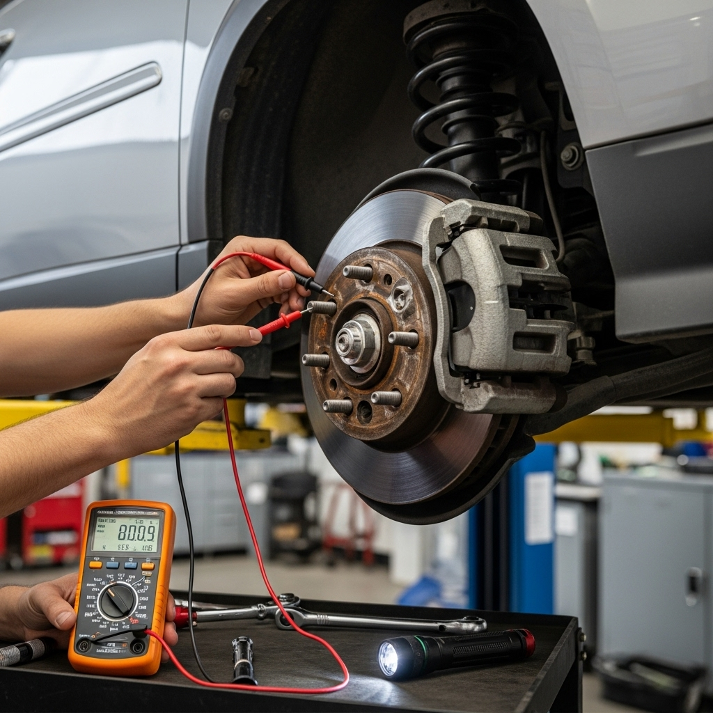
Method 2: Resistance Testing (Ohms)
Resistance testing checks the internal health of the wheel speed sensor. This is performed with the sensor disconnected from the vehicle’s wiring.
Procedure for Resistance Testing:
- Safely lift and support the vehicle, then remove the wheel for access
- Locate the wheel speed sensor and disconnect its electrical connector
- Set your multimeter to the resistance (Ohms) setting
- Connect the multimeter leads to the two terminals of the sensor itself (not the vehicle harness)
- Compare your reading to specifications
Expected Resistance Values:
- Most Buick Rendezvous wheel speed sensors should measure between 900 and 2,500 ohms
- A reading of 0 ohms indicates a shorted sensor
- A reading of OL or infinite resistance indicates an open circuit (failed sensor)
- Significant variation between sensors on the same vehicle can indicate a failing sensor even if within specification
Method 3: AC Voltage Output Testing
This test checks whether the sensor is generating a signal when the wheel is rotating. This is the most definitive test of sensor operation.
Procedure for AC Voltage Testing:
- Reconnect the sensor to the vehicle harness
- Use backprobe pins or carefully insert multimeter leads into the back of the connector to contact the terminals
- Set your multimeter to AC Volts (ACV) on a low scale (usually 2V or 20V)
- Safely raise the wheel off the ground using jack stands
- Spin the wheel by hand at a moderate speed while watching the multimeter
- A good sensor should produce at least 100mV (0.1V) AC, with reading increasing as wheel speed increases
Important Notes:
- The voltage will be very low when spinning by hand—typically 0.1-0.5V AC
- If you have access to a graphing multimeter or lab scope, you can observe the AC waveform, which should be a clean sine wave
- Significantly lower output from one sensor compared to others indicates a weak sensor
Method 4: DC Reference Voltage and Continuity Testing
This test checks the wiring between the ABS control module and the wheel speed sensor.
Testing Sensor Wiring and Module Communication:
- Disconnect the sensor electrical connector
- Turn the ignition to ON (engine off)
- Set multimeter to DC Volts
- Measure between the two terminals in the vehicle harness (not the sensor)
- You should measure approximately 2.5V DC or 12V DC, depending on system design
- No voltage may indicate wiring problems back to the ABS module
Continuity Testing to Check Wiring:
- With sensor disconnected at both ends (at wheel and at ABS module if possible)
- Check for continuity between ends of each wire
- Check for continuity between each wire and ground (there should be none)
Advanced Diagnostic Scenarios and Solutions
Sometimes the problem isn’t with the sensor itself, but with related components.
Diagnosing Intermittent Wheel Speed Sensor Issues
Intermittent faults can be the most challenging to diagnose. These often manifest as warning lights that come and go, or systems that work sometimes but not others.
Causes of Intermittent Issues:
- Loose or corroded electrical connections
- Wiring that’s damaged but not completely broken
- Sensors that fail only when hot
- Tone wheels with minor damage that only occasionally affects the signal
Diagnostic Approach for Intermittent Problems:
- Perform a thorough visual inspection of all wiring, looking for subtle damage
- Check connector security at both the sensor and ABS module
- Test sensor resistance when cold, then run vehicle and test when hot
- Use a scanner to monitor live wheel speed data while driving (requires helper)
- Gently wiggle wiring harnesses while monitoring sensor output
Tone Ring Inspection and Cleaning
The tone ring (or reluctor ring) is the toothed ring that the sensor reads. Problems with the tone ring can mimic sensor failures.
Tone Ring Inspection Procedure:
- Remove the wheel speed sensor
- Visually inspect the tone ring through the sensor mounting hole
- Look for missing teeth, cracks, or debris buildup
- Clean any metal debris or buildup with brake cleaner and a small brush
- Check for excessive runout or damage to the tone ring
Common Tone Ring Problems:
- Rust buildup between teeth (common in snowy regions where salt is used)
- Physical damage from road debris or improper service
- Corrosion that causes teeth to deteriorate
Repair and Replacement Procedures
Once you’ve identified a faulty wheel speed sensor, proper replacement is crucial.
Front Wheel Speed Sensor Replacement
Tools Needed:
- Socket set
- Torque wrench
- Jack and jack stands
- Possibly a pick or small pry tool
Replacement Steps:
- Safely lift and support the front of the vehicle, then remove the wheel
- Locate the sensor mounted in the steering knuckle
- Disconnect the electrical connector
- Remove the mounting bolt (typically one 10mm bolt)
- Gently pull the sensor from the knuckle—it may require light prying if corroded
- Clean the sensor mounting hole in the knuckle
- Apply a light coat of anti-seize to the new sensor’s mounting surface (not the tip)
- Install the new sensor and torque the bolt to specification (typically 8-10 ft-lbs)
- Reconnect the electrical connector
- Reinstall the wheel and lower the vehicle
- Clear diagnostic codes and test drive
Rear Wheel Speed Sensor Replacement
The rear sensors on Buick Rendezvous are typically integrated with the wheel bearing hub assembly, requiring full hub replacement.
Rear Sensor/Hub Assembly Replacement:
- Lift and support rear of vehicle, remove wheel
- Remove brake caliper and bracket (hang caliper safely without stressing hose)
- Remove brake rotor
- Remove hub mounting bolts (typically 4 bolts accessible from the back)
- Disconnect wheel speed sensor electrical connector
- Remove entire hub assembly
- Installation is reverse of removal
- Torque all fasteners to specification
- Reconnect electrical connector
- Reassemble brakes, install wheel, and lower vehicle
Post-Repair Testing and Verification
After replacing a wheel speed sensor, proper testing is essential to ensure the repair was successful.
Verification Procedure:
- Clear all ABS-related diagnostic trouble codes
- Start the engine and verify that all warning lights extinguish after initial bulb check
- Use a scanner to monitor live wheel speed data while driving
- All four wheels should show identical speeds during straight-line driving
- Test ABS functionality in a safe, controlled environment (empty parking lot)
- Perform several normal braking stops to ensure proper operation
- Test traction control if possible (on loose surface if available safely)
Preventive Maintenance and Long-Term Care
Proper maintenance can extend the life of your wheel speed sensors and prevent future failures.
Wheel Speed Sensor Maintenance Tips:
- Avoid damaging sensor wiring during tire changes or brake service
- Keep sensors clean of excessive debris and metal particles
- Address any brake fluid leaks promptly, as fluid can damage sensors
- Have your braking system inspected annually
- Fix any wheel bearing play immediately, as it can damage tone rings
Cost Considerations and Professional Help
Understanding when to DIY and when to seek professional assistance is important.
Cost Breakdown:
- Wheel speed sensor part: $50-$150 each
- Rear hub assembly (with integrated sensor): $150-$300 each
- Professional diagnosis: $80-$150
- Professional replacement labor: 1-2 hours per wheel
When to Seek Professional Help:
- If you’re uncomfortable with electrical diagnostics
- If the problem persists after sensor replacement
- If you don’t have access to proper tools or a scan tool
- If there are additional symptoms suggesting ABS module failure
Final Thoughts on How to Check Wheel Speed Sensors on Buick Rendezvous
Successfully diagnosing and repairing wheel speed sensor issues on your Buick Rendezvous requires methodical testing and attention to detail. By following the comprehensive procedures outlined in this guide—from initial code scanning through resistance and output voltage testing—you can accurately identify faulty sensors and restore your vehicle’s crucial safety systems.
Remember that while wheel speed sensors might seem like small components, they play an enormous role in your vehicle’s safety. Proper diagnosis and repair not only extinguish those annoying dashboard lights but, more importantly, restore the ABS, traction control, and stability systems that could one day prevent an accident.
With the knowledge from this guide, you’re now equipped to tackle one of the most common issues affecting the Buick Rendezvous, saving yourself significant repair costs while ensuring your vehicle remains safe for you and your family.

![Detroit Axle - RWD Shock Absorbers for 1999-2006 Chevy Silverado GMC Sierra 1500 [Without Electronic Suspension], 4 Shock Absorbers Front and Rear 2000 2001 2002 2003 2004 2005 Replacement #1](https://m.media-amazon.com/images/I/51kGoxd6WKL._SL100_.jpg)
![Detroit Axle - RWD Shock Absorbers for 1999-2006 Chevy Silverado GMC Sierra 1500 [Without Electronic Suspension], 4 Shock Absorbers Front and Rear 2000 2001 2002 2003 2004 2005 Replacement #2](https://m.media-amazon.com/images/I/41hNXiRwHoL._SL100_.jpg)
![Detroit Axle - RWD Shock Absorbers for 1999-2006 Chevy Silverado GMC Sierra 1500 [Without Electronic Suspension], 4 Shock Absorbers Front and Rear 2000 2001 2002 2003 2004 2005 Replacement #3](https://m.media-amazon.com/images/I/51KWNAdZdTL._SL100_.jpg)
![Detroit Axle - RWD Shock Absorbers for 1999-2006 Chevy Silverado GMC Sierra 1500 [Without Electronic Suspension], 4 Shock Absorbers Front and Rear 2000 2001 2002 2003 2004 2005 Replacement #4](https://m.media-amazon.com/images/I/31Bu2iIdhgS._SL100_.jpg)
![Detroit Axle - RWD Shock Absorbers for 1999-2006 Chevy Silverado GMC Sierra 1500 [Without Electronic Suspension], 4 Shock Absorbers Front and Rear 2000 2001 2002 2003 2004 2005 Replacement #5](https://m.media-amazon.com/images/I/416OO4h1jyL._SL100_.jpg)
