Table of Contents
Imagine being stranded miles from help with a disabled vehicle. Your primary recovery tool suddenly stops responding. Could understanding its electrical components become your lifeline? This guide reveals critical insights for off-road enthusiasts facing urgent mechanical challenges.
Modern recovery systems rely on precise electrical connections. When standard controls malfunction, knowing how to maintain functionality becomes essential. We focus on practical solutions for extreme situations where conventional methods fall short.
Safety remains paramount when working with high-current systems. Proper preparation prevents accidents and ensures reliable results. You’ll discover how to assess your equipment’s needs and execute vital procedures correctly.
Key Takeaways
- Recognize situations requiring immediate electrical system intervention
- Master essential safety protocols for high-current equipment handling
- Identify required tools for emergency power routing solutions
- Differentiate between temporary fixes and long-term system modifications
- Understand core principles of motor control mechanisms
This section prepares you for subsequent technical instructions while emphasizing responsible equipment management. The skills covered could mean the difference between swift recovery and prolonged wilderness challenges.
Understanding Winch Solenoid Fundamentals
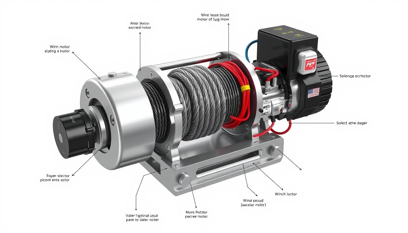
Vehicle recovery systems depend on precise electrical connections to function properly. At the heart of these systems lies a critical electromagnetic device that manages power distribution. This component’s failure can leave operators stranded in challenging environments.
Electromagnetic Power Routing Explained
The core electrical switch uses magnetic fields to connect battery power to the recovery motor. Three primary terminals handle different current pathways – two for directional control and one for power input. When activated, these connections create specific motor rotations for cable management.
Critical Failure Patterns
Environmental exposure often damages these components. Moisture infiltration causes terminal corrosion, while repeated heavy loads can warp internal contacts. Operators might hear rapid clicking sounds or experience partial system response during failure events.
Manufacturers like those near Crafers West design systems with standardized terminal layouts. This allows consistent troubleshooting methods across different models. Proper diagnosis separates control issues from actual component failures, guiding effective solutions.
Regular maintenance checks prevent 55% of field failures according to recovery specialists. Cleaning terminals and inspecting connections should occur after every major operation. These practices extend component lifespan significantly.
Bypass Winch Solenoid Process Overview
When critical components fail during recovery operations, direct power routing becomes essential. This method maintains motor functionality through manual electrical connections. Proper execution requires understanding three-terminal systems and directional polarity principles.

Preparation and Safety Considerations
Disconnect the positive battery lead first to prevent accidental activation. Wear insulated gloves and clear the work area of conductive materials. Verify your tools match the terminal sizes for secure connections.
Step-by-Step Instructions for Manual Activation
Locate the three primary terminals marked on the control unit. Attach a jumper wire from the battery’s positive post to the desired motor terminal. Maintain the negative connection through existing wiring for circuit completion.
Reverse drum rotation by moving the jumper to the alternate terminal. Always test connections briefly before full engagement. Store extra leads in your recovery kit for repeated adjustments.
Addressing Operational Challenges
Common issues stem from poor contact or depleted power sources. Clean terminals with abrasive cloth if sparking occurs. Use this table to diagnose frequent problems:
| Issue | Likely Cause | Solution |
|---|---|---|
| No motor response | Loose jumper connection | Retighten all terminals |
| Intermittent operation | Corroded contact points | Clean with wire brush |
| Single direction only | Incorrect terminal selection | Swap jumper position |
If problems persist after troubleshooting, consult manufacturer guidelines dated April 2009 for specific component diagrams. Field repairs require constant awareness of thermal buildup in unprotected circuits.
Tools, Components, and Additional Techniques
What separates successful field repairs from dangerous improvisation? Proper equipment selection makes all the difference when managing electrical systems. Quality materials ensure safe power transfer while protecting sensitive components.
Essential Field Repair Kit
High-grade jumper cables (10-gauge minimum) handle intense current flows. Insulated tools prevent accidental shorts during adjustments. A multimeter helps verify connections before energizing circuits.
Corrosion-resistant battery clamps maintain conductivity in wet conditions. Dielectric grease protects terminals from moisture damage. Always carry spare fuses matching your system’s specifications – they act as critical safety buffers.
| Solution Type | Components Needed | Best Use Case |
|---|---|---|
| Temporary Fix | Jumper wires, electrical tape | Emergency recoveries |
| Permanent Setup | Weatherproof switches, circuit breakers | Frequent off-road use |
| Backup System | Portable control pack, schematic diagrams | Extended expeditions |
Techniques vary by situation. For Crafers West South AustraliaPosts 11,732 total users, documentation from 31st July 2011 shows modified approaches for Adelaide Hills terrain. Local operators often keep spare parts like those mentioned in SAPosts 12,486 total downloaded guides.
“Field modifications require understanding direction power applied principles – never bypass protective systems without voltage verification.”
Advanced users install auxiliary switches that maintain original wiring integrity. These setups let operators choose between standard controls and manual override. Always test new configurations with low loads first.
Conclusion
When standard systems fail, a clear understanding of electrical principles becomes crucial. Mastering these emergency procedures ensures you maintain control during critical recovery scenarios. Always prioritize safety protocols and verify connections before activating modified circuits.
The tm-2 engine saver proves invaluable for monitoring system health during temporary fixes. Pair this tool with proper insulation materials to reduce risks. For complex issues, consult the engine saver reply database from trusted off-road communities.
This guide equips you with core skills for emergency motor activation and diagnostics. While effective short-term, these methods shouldn’t replace professional repairs. Schedule component replacements immediately after stabilization.
Adventure preparedness means balancing quick solutions with long-term equipment care. Store a tm-2 engine saver in your kit alongside repair manuals. With practice, you’ll handle unexpected challenges confidently while protecting your gear’s lifespan.
FAQ
Why would I need to bypass an electrical switch on my recovery tool?
What safety steps should I take before modifying the electrical system?
How do I identify the correct terminals for direct power routing?
What tools are essential for emergency power rerouting?
Why does my equipment only move in one direction after rerouting power?
Can I leave this modification as a permanent solution?
What indicates a motor problem versus a switch failure?


Chemical Guys Total Interior Cleaner & Protectant Interior Cleaner, Cleans & Protects Leather, Vinyl, Plastic, Rubber, Glass with a Streak-Free Finish — Cars, Trucks, SUVs, RVs, 16 oz
$11.97 (as of April 4, 2026 11:18 GMT +00:00 - More infoProduct prices and availability are accurate as of the date/time indicated and are subject to change. Any price and availability information displayed on [relevant Amazon Site(s), as applicable] at the time of purchase will apply to the purchase of this product.)


AUTOBOO 26" and 16" Windshield Wipers Blades (Pack Of 2),OEM Quality Premium All-Seasons Wiper blades,Stable and Quiet Armor wiper blades
$16.99 (as of April 4, 2026 10:14 GMT +00:00 - More infoProduct prices and availability are accurate as of the date/time indicated and are subject to change. Any price and availability information displayed on [relevant Amazon Site(s), as applicable] at the time of purchase will apply to the purchase of this product.)


Valvoline MaxLife High Mileage 5W-30 Synthetic Blend Motor Oil 5 Quart
$19.97 (as of April 4, 2026 10:32 GMT +00:00 - More infoProduct prices and availability are accurate as of the date/time indicated and are subject to change. Any price and availability information displayed on [relevant Amazon Site(s), as applicable] at the time of purchase will apply to the purchase of this product.)


MAX Advanced Brakes - Brake Kit For 2011-2016 Hyundai Elantra, 2014-2018 Kia Forte| Carbon Ceramic Brake and Rotor Kit Front and Rear| OE Replacement Brake Rotors
$162.99 (as of April 4, 2026 05:15 GMT +00:00 - More infoProduct prices and availability are accurate as of the date/time indicated and are subject to change. Any price and availability information displayed on [relevant Amazon Site(s), as applicable] at the time of purchase will apply to the purchase of this product.)


USANOOKS Microfiber Cleaning Cloth Grey - 12 Pcs (12.5"x12.5") - High Performance - 1200 Washes, Ultra Absorbent Microfiber Towel Weave Grime & Liquid for Streak-Free Mirror Shine - Car Washing Cloth
$6.98 (as of April 4, 2026 13:08 GMT +00:00 - More infoProduct prices and availability are accurate as of the date/time indicated and are subject to change. Any price and availability information displayed on [relevant Amazon Site(s), as applicable] at the time of purchase will apply to the purchase of this product.)


Car Clip Pliers, Panel Clip Removal Pliers, Professional Plastic Fastener Removal Tool for Removing Automotive Fasteners Clips Without Damage
$19.99 (as of April 4, 2026 11:47 GMT +00:00 - More infoProduct prices and availability are accurate as of the date/time indicated and are subject to change. Any price and availability information displayed on [relevant Amazon Site(s), as applicable] at the time of purchase will apply to the purchase of this product.)


AUXITO Latest 194 LED Bulbs Amber Yellow, Canbus Error Free 168 2825 T10 W5W LED Bulb for Car Dome Door Map Courtesy Trunk Cargo Marker License Plate Exterior Lights, Pack of 2
$8.78 (as of April 4, 2026 10:11 GMT +00:00 - More infoProduct prices and availability are accurate as of the date/time indicated and are subject to change. Any price and availability information displayed on [relevant Amazon Site(s), as applicable] at the time of purchase will apply to the purchase of this product.)


GIMWA Collapsible Wash Basin with Drain Plug - 2.4 Gallon Foldable Kitchen Sink for Baby Bottles, RV Camping, Space-Saving Dish Tub (Gray)
$16.50 (as of April 4, 2026 10:08 GMT +00:00 - More infoProduct prices and availability are accurate as of the date/time indicated and are subject to change. Any price and availability information displayed on [relevant Amazon Site(s), as applicable] at the time of purchase will apply to the purchase of this product.)


BOSCH 18A18A ICON Beam Wiper Blades - Driver and Passenger Side - Set of 2 Blades (18A & 18A)
$37.48 (as of April 4, 2026 10:10 GMT +00:00 - More infoProduct prices and availability are accurate as of the date/time indicated and are subject to change. Any price and availability information displayed on [relevant Amazon Site(s), as applicable] at the time of purchase will apply to the purchase of this product.)